This is the multi-page printable view of this section. Click here to print.
Layout Engines
- 1: dot
- 2: neato
- 3: fdp
- 4: sfdp
- 5: circo
- 6: twopi
- 7: nop
- 8: nop2
- 9: osage
- 10: patchwork
- 11: Writing Layout Plugins
1 - dot
dot is the default tool to use if edges have directionality.
The layout algorithm aims edges in the same direction (top to bottom, or left to right) and then attempts to avoid edge crossings and reduce edge length.
- PDF Manual
- User Guide (caveat: not current with latest features of Graphviz)
- Browse code

Attributes for dot features
- clusterrank – Mode used for handling clusters. Valid on: Graphs.
- compound – If true, allow edges between clusters. Valid on: Graphs.
- constraint – If false, the edge is not used in ranking the nodes. Valid on: Edges.
- group – Name for a group of nodes, for bundling edges avoiding crossings.. Valid on: Nodes.
- lhead – Logical head of an edge. Valid on: Edges.
- ltail – Logical tail of an edge. Valid on: Edges.
- mclimit – Scale factor for mincross (mc) edge crossing minimizer parameters. Valid on: Graphs.
- minlen – Minimum edge length (rank difference between head and tail). Valid on: Edges.
- newrank – Whether to use a single global ranking, ignoring clusters. Valid on: Graphs.
- nslimit – Sets number of iterations in network simplex applications. Valid on: Graphs.
- nslimit1 – Sets number of iterations in network simplex applications. Valid on: Graphs.
- ordering – Constrains the left-to-right ordering of node edges.. Valid on: Graphs, Nodes.
- rank – Rank constraints on the nodes in a subgraph. Valid on: Subgraphs.
- rankdir – Sets direction of graph layout. Valid on: Graphs.
- ranksep – Specifies separation between ranks. Valid on: Graphs.
- remincross – If there are multiple clusters, whether to run edge crossing minimization a second time.. Valid on: Graphs.
-
samehead
–
Edges with the same head and the same
sameheadvalue are aimed at the same point on the head. Valid on: Edges. -
sametail
–
Edges with the same tail and the same
sametailvalue are aimed at the same point on the tail.. Valid on: Edges. - searchsize – During network simplex, the maximum number of edges with negative cut values to search when looking for an edge with minimum cut value.. Valid on: Graphs.
- showboxes – Print guide boxes for debugging. Valid on: Edges, Nodes, Graphs.
- TBbalance – Which rank to move floating (loose) nodes to. Valid on: Graphs.
2 - neato
neato is a reasonable default tool to use for undirected graphs that aren't
too large (about 100 nodes), when you don't know anything else about the graph.
neato attempts to minimize a global energy function, which is equivalent to
statistical multi-dimensional scaling.
The solution is achieved using stress majorization1, though the older
Kamada-Kawai algorithm2, using steepest descent, is also available,
by switching mode.
- PDF Manual
- User Guide (caveat: not current with latest features of Graphviz)
- Browse code
- Gallery

Attributes for neato features
- Damping – Factor damping force motions.. Valid on: Graphs.
- defaultdist – The distance between nodes in separate connected components. Valid on: Graphs.
- dim – Set the number of dimensions used for the layout. Valid on: Graphs.
- dimen – Set the number of dimensions used for rendering. Valid on: Graphs.
- diredgeconstraints – Whether to constrain most edges to point downwards. Valid on: Graphs.
- epsilon – Terminating condition. Valid on: Graphs.
- esep – Margin used around polygons for purposes of spline edge routing. Valid on: Graphs.
- inputscale – Scales the input positions to convert between length units. Valid on: Graphs.
- len – Preferred edge length, in inches. Valid on: Edges.
- levelsgap – strictness of neato level constraints. Valid on: Graphs.
- maxiter – Sets the number of iterations used. Valid on: Graphs.
- mode – Technique for optimizing the layout. Valid on: Graphs.
- model – Specifies how the distance matrix is computed for the input graph. Valid on: Graphs.
- normalize – normalizes coordinates of final layout. Valid on: Graphs.
- notranslate – Whether to avoid translating layout to the origin point. Valid on: Graphs.
- overlap – Determines if and how node overlaps should be removed. Valid on: Graphs.
- overlap_scaling – Scale layout by factor, to reduce node overlap.. Valid on: Graphs.
- pin – Keeps the node at the node's given input position. Valid on: Nodes.
- pos – Position of node, or spline control points. Valid on: Edges, Nodes.
- scale – Scales layout by the given factor after the initial layout. Valid on: Graphs.
- sep – Margin to leave around nodes when removing node overlap. Valid on: Graphs.
- start – Parameter used to determine the initial layout of nodes. Valid on: Graphs.
- voro_margin – Tuning margin of Voronoi technique. Valid on: Graphs.
-
Gansner, E.R., Koren, Y., North, S. (2005). Graph Drawing by Stress Majorization. In: Pach, J. (eds) Graph Drawing. GD 2004. Lecture Notes in Computer Science, vol 3383. Springer, Berlin, Heidelberg. ↩︎
-
Tomihisa Kamada, Satoru Kawai, An algorithm for drawing general undirected graphs, Information Processing Letters, Volume 31, Issue 1, 1989, Pages 7-15. ↩︎
3 - fdp
spring model layouts similar to those of neato, but does this by reducing forces rather than working with energy.
fdp implements the Fruchterman-Reingold heuristic1 including a multigrid solver
that handles larger graphs and clustered undirected graphs.

Attributes for fdp features
- dim – Set the number of dimensions used for the layout. Valid on: Graphs.
- dimen – Set the number of dimensions used for rendering. Valid on: Graphs.
- inputscale – Scales the input positions to convert between length units. Valid on: Graphs.
- K – Spring constant used in virtual physical model. Valid on: Graphs, Clusters.
- len – Preferred edge length, in inches. Valid on: Edges.
- maxiter – Sets the number of iterations used. Valid on: Graphs.
- normalize – normalizes coordinates of final layout. Valid on: Graphs.
- overlap_scaling – Scale layout by factor, to reduce node overlap.. Valid on: Graphs.
- pin – Keeps the node at the node's given input position. Valid on: Nodes.
- pos – Position of node, or spline control points. Valid on: Edges, Nodes.
- sep – Margin to leave around nodes when removing node overlap. Valid on: Graphs.
- start – Parameter used to determine the initial layout of nodes. Valid on: Graphs.
4 - sfdp
sfdp is a fast, multilevel, force-directed algorithm that efficiently layouts large graphs, outlined in "Efficient and High Quality Force-Directed Graph Drawing"1.
Multiscale version of the fdp layout, for the layout of large graphs.
Attributes for sfdp features
- beautify – Whether to draw leaf nodes uniformly in a circle around the root node in sfdp.. Valid on: Graphs.
- dim – Set the number of dimensions used for the layout. Valid on: Graphs.
- dimen – Set the number of dimensions used for rendering. Valid on: Graphs.
- K – Spring constant used in virtual physical model. Valid on: Graphs, Clusters.
-
label_scheme
–
Whether to treat a node whose name has the form
|edgelabel|*as a special node representing an edge label.. Valid on: Graphs. - levels – Number of levels allowed in the multilevel scheme. Valid on: Graphs.
- normalize – normalizes coordinates of final layout. Valid on: Graphs.
- overlap_scaling – Scale layout by factor, to reduce node overlap.. Valid on: Graphs.
- overlap_shrink – Whether the overlap removal algorithm should perform a compression pass to reduce the size of the layout. Valid on: Graphs.
- quadtree – Quadtree scheme to use. Valid on: Graphs.
- repulsiveforce – The power of the repulsive force used in an extended Fruchterman-Reingold. Valid on: Graphs.
- rotation – Rotates the final layout counter-clockwise by the specified number of degrees. Valid on: Graphs.
- smoothing – Specifies a post-processing step used to smooth out an uneven distribution of nodes.. Valid on: Graphs.
- start – Parameter used to determine the initial layout of nodes. Valid on: Graphs.
- voro_margin – Tuning margin of Voronoi technique. Valid on: Graphs.
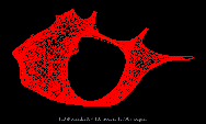
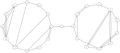
5 - circo
After Six and Tollis 199912, Kauffman and Wiese 20023.
This is suitable for certain diagrams of multiple cyclic structures, such as certain telecommunications networks.
Attributes for circo features
- mindist – Specifies the minimum separation between all nodes. Valid on: Graphs.
- root – Specifies nodes to be used as the center of the layout. Valid on: Graphs, Nodes.
- normalize – normalizes coordinates of final layout. Valid on: Graphs.
- oneblock – Whether to draw circo graphs around one circle.. Valid on: Graphs.
- overlap_scaling – Scale layout by factor, to reduce node overlap.. Valid on: Graphs.
- voro_margin – Tuning margin of Voronoi technique. Valid on: Graphs.
-
Six J.M., Tollis I.G. (1999) A Framework for Circular Drawings of Networks. In: Kratochvíyl J. (eds) Graph Drawing. GD 1999. Lecture Notes in Computer Science, vol 1731. Springer, Berlin, Heidelberg. ↩︎
-
Six J.M., Tollis I.G. (1999) Circular Drawings of Biconnected Graphs. In: Goodrich M.T., McGeoch C.C. (eds) Algorithm Engineering and Experimentation. ALENEX 1999. Lecture Notes in Computer Science, vol 1619. Springer, Berlin, Heidelberg. ↩︎
-
Michael Kaufmann, Roland Wiese (2002) Embedding Vertices at Points: Few Bends suffice for Planar Graphs. In: Journal of Graph Algorithms and Applications. vol. 6, no. 1, pp. 115–129 ↩︎
6 - twopi
After Graham Wills 19971.
Nodes are placed on concentric circles depending their distance from a given root node.
You can set the root node, or let twopi do it.

Attributes for twopi features
- normalize – normalizes coordinates of final layout. Valid on: Graphs.
- overlap_scaling – Scale layout by factor, to reduce node overlap.. Valid on: Graphs.
- ranksep – Specifies separation between ranks. Valid on: Graphs.
- root – Specifies nodes to be used as the center of the layout. Valid on: Graphs, Nodes.
- voro_margin – Tuning margin of Voronoi technique. Valid on: Graphs.
- weight – Weight of edge. Valid on: Edges.
7 - nop
nop1.Prints input graphs in pretty-printed (canonical) form.
Example, indenting the input:
$ echo 'digraph { a -> b; c->d; }' | nop
digraph {
        a -> b;
        c -> d;
}
nop also deduplicates node specifications:
$ echo 'digraph { a; a [label="A"]; a [color=blue]; }' | nop
digraph {
        a       [color=blue,
                label=A];
}
nop -p produces no output, just checks the input for valid DOT language.
For example, this valid graph produces no output:
$ echo 'digraph {}' | nop -p
But this syntax error (missing }) exits with status code 1 and prints error
message:
$ echo 'digraph {' | nop -p
Error: <stdin>: syntax error in line 2
8 - nop2
Invoke equivalently as:
neato -n2dot -Knop2
Assumes positions already specified in the input with the pos attribute.
This performs an optional adjustment to remove node-node overlap, computes edge layouts, and emites the graphs.
9 - osage
As input, osage takes any graph in the dot format.
osage draws the graph recursively. At each level, there will be a collection of
nodes and a collection of cluster subgraphs. The internals of each cluster
subgraph are laid out, then the cluster subgraphs and nodes at the current
level are positioned relative to each other, treating each cluster subgraph as
a node.
At each level, the nodes and cluster subgraphs are viewed as rectangles to be
packed together. At present, edges are ignored during packing. Packing is done
using the standard packing functions. In particular, the graph attributes
pack and packmode control the layout. Each graph and cluster can
specify its own values for these attributes. Remember also that a cluster
inherits its attribute values from its parent graph.
After all nodes and clusters, edges are routed based on the value of the
splines attribute.
Example:

graph {
	layout=osage
		subgraph cluster_0 {
			label="composite cluster";
			subgraph cluster_1 {
			    label="the first cluster";
				C
				L
				U
				S
				T
				E
				R
			}
			subgraph cluster_2 {
			    label="the second\ncluster";
				a
				b
				c
				d
			}
			1
			2
		}
	3
	4
	5
}10 - patchwork
Each cluster is given an area based on the areas specified by the clusters and
nodes it contains. The areas of nodes and empty clusters can be specified by
the area attribute. The default area
is 1.
The root graph is laid out as a square. Then, recursively, the region of a cluster or graph is partitioned among its top-level nodes and clusters, with each given a roughly square subregion with its specified area.
Example: Australian Coins, area proportional to value

graph {
	layout=patchwork
	node [style=filled]
	"$2"  [area=200 fillcolor=gold]
	"$1"  [area=100 fillcolor=gold]
	"50c" [area= 50 fillcolor=silver]
	"20c" [area= 20 fillcolor=silver]
	"10c" [area= 10 fillcolor=silver]
	"5c"  [area=  5 fillcolor=silver]
}Attributes for patchwork features
- area – Indicates the preferred area for a node or empty cluster. Valid on: Nodes, Clusters.
11 - Writing Layout Plugins
To create a new layout plugin called xxx, you first need
to provide two functions: xxx_layout and xxx_cleanup. The
semantics of these are described below.
Layout
void xxx_layout(Agraph_t *g)
Initialize the graph.
-
If the algorithm will use the common edge routing code, it should call
setEdgeType(g, ...);. -
For each node, call
common_init_nodeandgv_nodesize. -
If the algorithm will use
spline_edges()to route the edges, the node coordinates need to be stored inND_pos, so this should be allocated here. This, and the two calls mentioned above, are all handled by a call toneato_init_node(). -
For each edge, call
common_init_edge. -
The algorithm should allocate whatever other data structures it needs. This can involve fields in the
A*info_tfields. In addition, each of these fields contains avoid *alg;subfield that the algorithm can use the store additional data. -
Layout the graph. When finished, each node should have its coordinates stored in points in
ND_coord_i(n), each edge should have its layout described inED_spl(e). (N.B. As of version 2.21,ND_coord_ihas been replaced byND_coord, which are now floating point coordinates.)
To add edges, there are 3 functions available:
spline_edges1(Agraph_t *, int edgeType)Assumes the node coordinates are stored inND_coord_i, and thatGD_bbis set. For each edge, this function constructs the appropriate data and stores it inED_spl.spline_edges0(Agraph_t *)Assumes the node coordinates are stored inND_pos, and thatGD_bbis set. This function uses the ratio attribute if set, copies the values inND_postoND_coord_i(converting from inches to points); and callsspline_edges1using the edge type specified bysetEdgeType().spline_edges(Agraph_t *)Assumes the node coordinates are stored inND_pos. This function calculates the bounding box of g and stores it inGD_bb, then callsspline_edges0().
If the algorithm only works with connected components, the code can
use the pack library to get components, lay them out individually, and
pack them together based on user specifications. A typical schema is
given below. One can look at the code for twopi, circo, neato or fdp
for more detailed examples.
int ncc;

Agraph_t **ccs = ccomps(g, &ncc, 0);
if (ncc == 1) {
  // layout nodes of g
  adjustNodes(g); // if you need to remove overlaps
  spline_edges(g); // generic edge routing code

} else {
  pack_info pinfo;
  pack_mode pmode = getPackMode(g, l_node);

  for (int i = 0; i < ncc; i++) {
      Agraph_t *const sg = ccs[i];
      // layout sg
      adjustNodes(sg); // if you need to remove overlaps
  }
  spline_edges(g); // generic edge routing

  // initialize packing info, e.g.
  pinfo.margin = getPack(g, CL_OFFSET, CL_OFFSET);
  pinfo.doSplines = 1;
  pinfo.mode = pmode;
  pinfo.fixed = 0;
  packSubgraphs(ncc, ccs, g, &pinfo);
}
for (int i = 0; i < ncc; i++) {
  agdelete(g, ccs[i]);
}

free(ccs);
Be careful in laying out subgraphs if you rely on attributes that have only been set in the root graph. With connected components, edges can be added with each component, before packing (as above) or after the components have been packed (see circo).
It is good to check for trivial cases where the graph has 0 or 1 nodes, or no edges.
At the end of xxx_layout, call
dotneato_postprocess(g);
The following template will work in most cases, ignoring the problems of handling disconnected graphs and removing node overlaps:
static void xxx_init_node(node_t *n) {
  neato_init_node(n);
  // add algorithm-specific data, if desired
}

static void xxx_init_edge(edge_t *e) {
  common_init_edge(e);
  // add algorithm-specific data, if desired
}

static void xxx_init_node_edge(graph_t *g) {
  for (node_t *n = agfstnode(g); n; n = agnxtnode(g, n)) {
    xxx_init_node(n);
  }
  for (node_t *n = agfstnode(g); n; n = agnxtnode(g, n)) {
    for (edge_t *e = agfstout(g, n); e; e = agnxtout(g, e)){
      xxx_init_edge(e);
    }
  }
}

void xxx_layout (Agraph_t *g) {
  xxx_init_node_edge(g);
  // Set ND_pos(n) for each node n
  spline_edges(g);
  dotneato_postprocess(g);
}
Cleanup
void xxx_cleanup(Agraph_t *g)
Free up any resources allocated in the layout.
Finish with calls to gv_cleanup_node and gv_cleanup_edge for
each node and edge. This cleans up splines labels, ND_pos, shapes
and 0's out the A*info_t, so these have to occur last, but could be
part of explicit xxx_cleanup_node and xxx_cleanup_edge, if desired.
At the end, you should do:
if (g != g->root) memset(&g->u, 0, sizeof(Agraphinfo_t));
This is necessary for the graph to be laid out again, as the layout code assumes this structure is clean.
libgvc does a final cleanup to the root graph, freeing any drawing,
freeing its label, and zeroing out Agraphinfo_t of the root graph.
The following template will work in most cases:
static void xxx_cleanup_graph(Agraph_t *g) {
  // Free any algorithm-specific data attached to the graph
  if (g != g->root) memset(&g->u, 0, sizeof(Agraphinfo_t));
}

static void xxx_cleanup_edge (Agedge_t *e) {
  // Free any algorithm-specific data attached to the edge
  gv_cleanup_edge(e);
}

static void xxx_cleanup_node(Agnode_t *n) {
  // Free any algorithm-specific data attached to the node
  gv_cleanup_node(e);
}

void xxx_cleanup(Agraph_t *g) {
  for (Agnode_t *n = agfstnode(g); n; n = agnxtnode(g, n)) {
    for (Agedge_t *e = agfstout(g, n); e; e = agnxtout(g, e)) {
      xxx_cleanup_edge(e);
    }
    xxx_cleanup_node(n);
  }
  xxx_cleanup_graph(g);
}
Most layouts use auxiliary routines similar to neato, so
the entry points can be added in plugin/neato_layout.
Add to gvlayout_neato_layout.c:
gvlayout_engine_t xxxgen_engine = {
  xxx_layout,
  xxx_cleanup,
};
and the line
{LAYOUT_XXX, "xxx", 0, &xxxgen_engine, &(gvlayout_features_t){0}},
to gvlayout_neato_types and a new emum LAYOUT_XXX to layout_type in that file.
The above allows the new layout to piggyback on top of the neato
plugin, but requires rebuilding the plugin. In general, a user
can (and probably should) build a layout plugin totally separately.
To do this, after writing xxx_layout and xxx_cleanup, it is necessary to:
-
Add the types and data structures:
typedef enum { LAYOUT_XXX } layout_type; gvlayout_engine_t xxxgen_engine = { xxx_layout, xxx_cleanup, }; static gvplugin_installed_t gvlayout_xxx_types[] = { {LAYOUT_XXX, "xxx", 0, &xxxgen_engine, &(gvlayout_features_t){0}}, {0} }; static gvplugin_api_t apis[] = { {API_layout, &gvlayout_xxx_types}, {0}, }; gvplugin_library_t gvplugin_xxx_layout_LTX_library = { "xxx_layout", apis }; -
Combine all of this into a dynamic library whose name contains the string
gvplugin_and install the library in the same directory as the other Graphviz plugins. For example, on Linux systems, the dot layout plugin is in the librarylibgvplugin_dot_layout.so. -
Run
dot -cto regenerate the config file.
NOTES:
- Additional layouts can be added as extra lines in
gvlayout_xxx_types. - Obviously, most of the names and strings can be arbitrary. One
constraint is that external identifier for the
gvplugin_library_ttype must end in_LTX_library. In addition, the stringxxxin each entry ofgvlayout_xxx_typesis the name used to identify the layout algorithm, so needs to be distinct from any other layout name. - The features of a layout algorithm are currently limited to a
flag of bits, and the only flag supported is
LAYOUT_USES_RANKDIR, which enables the layout to therankdirattribute.
Changes need to be made to any applications that statically know about layout algorithms.
Automake Configuration
If you want to integrate your code into the Graphviz software and use its build system, follow the instructions below. You can certainly build and install your plugin using your own build software.
- Put your software in
lib/xxxgen, and added the hooks describe above intogvlayout_neato_layout.c - In
lib/xxxgen, provide aMakefile.am(based on a simple example likelib/fdpgen/Makefile.am) - In
lib/Makefile.am, addxxxgentoSUBDIRS - In
configure.ac, addlib/xxxgen/MakefiletoAC_CONFIG_FILES. - In
lib/plugin/neato_layout/Makefile.am, insert$(top_builddir)/lib/xxxgen/libxxxgen_C.lainlibgvplugin_neato_layout_C_la_LIBADD. - Remember to run
autogen.shbecause on its ownconfigurecan guess wrong.
This also assumes you have a good version of the various automake tools on your system.